Weapon Creation, 3D model step by step!
To create my 3D model of my weapon I opened Autodesk Maya, so that I could use the software.
First, when the software opens, I selected the ‘view’ button in the ‘front view’ and then I went down to the ‘Select Camera’ option.

Then this options bar appears on the right of the screen. Scroll down to the option that says ‘environment’ and then see where it says ‘image plane’ and click on ‘create’.

Then go to the bit where it allows you to browse your files, this is under ‘Image name’ then click on the little thumbnail that looks like a folder.

This window will then appear and allow you to pick an image from your folders. In the right of this new window. It will show you the image that you have just clicked to put into the Maya softwear.

After that these new options appear, this is so that you can manipulate the images, moving it in the axis and also so that you can change the size.
To do this you do it in the ‘Center’ and this changes the position of the image plane in the ‘X,Y and Z’ axis you may have to use minus numbers depending on the positioning of the image plane. The size is changed in the ‘Height’ and ‘Width’.


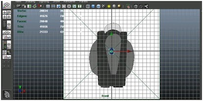
This is a print screen of the image plane in the software.

This is a print screen of all the image planes that I wanted in there so that I can start to create the model. I created these image planes in the same way that I created in the first view, I just made sure that the images were in the corresponding views. (front/top [I put this at the bottom so that when I am creating it I could create it over the top and I could also see the image plane]/side)

Now that they are set up in the way that I want them I can get started on the actual model itself.
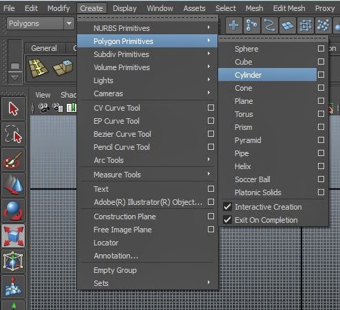
To start the model I made sure that options was in the ‘Polygons’ setting. Then went to the dropdown menu ‘Create’ – ‘Polygon Primitives’ – ‘Cube’.

Then after that is made I used the ‘Scale tool’ that is on the tool bar on the far left and manipulated the size and shape of the cube.


Then I used the ‘split select edge tool’.

This puts more edges into the modle so that I can manipulate the image even more by grabbing faces, edges and vetexis and moving and changing the size of them.


By right clicking on the mouse while it hovers over the image, this small quick step menu appears and you can click on edge, face and vertex, but I am going to click on ‘egde’ because those are what I want to work with first.

Then using the ‘Move tool’ on the edge that you have selected. Using the arrows that you can see, you can move the edge along the ‘X,Y and Z’ axis. As you can see from the image below, I have started with the top left corner and I have moved it inwards, this is because I want my weapon to have a more rounded type look, I will then create a pointed top in the top left of the cube.


This is how it looked after I manipulated the edges into a more naginata blade shape. I pinched in the right end of the barrel and rounded and also pointed the left side of the barrel.

I then got the ‘Split selected edge ring’ tool and click on the top edge and place one near the right and the left to make the object look like it has a border. Then click on the ‘Select tool’ to make sure that the splitting tool has been de-selected.

Then right click the mouse while hovering over the object and select face.

Then select, while holding shift, the centre faces.

Then click the ‘extrude’ tool.
Then using the ‘Move tool’ make the faces intrude into the shape, but make sure that the faces do not go too far into the object because otherwise it may distort the image too much and it will look horrible.

I have clicked number ‘3’ on my keyboard to make the object have a smoother surface, however to keep it like this when it’s finally rendered, I have to make sure that I have selected the object, and then I will go to the ‘Modify’ drop down list, to ‘Convert’ and then click ‘Smooth Mesh Preview to Polygons’.

You will then be able to see the increase in polygons in the object.

I am now going to create the bottom of the blade that will be connected to the shaft of the gun.
I start off by creating a cube.

After that I then shift the object using the ‘move tool’ so that it is connected to the bottom of the barrel of the gun. I then used the scale tool so that is was more of a cuboid shape, I then used the ‘split edge tool’ that we used earlier and at both ends of the object I made it so that there was a cube shape basically at each end. I then selected the faces that you can see in the image below using the shift button as you do so, so that you can select more than one face.

Then I clicked the ‘extrude tool’ and using the ‘move tool’ I extracted the faces from the object.

I only brought the faces out a little bit, I then clicking the ‘extrude tool’ again, scale down the surface area with the ‘scale tool’ and then with the ‘move tool’ bring out the face again and as you can see the block has been pinched at the ends.
After that click the ‘select tool’ and then go back and right click the image and select ‘face’ again and then select one of the smaller faces and sing the move tool make it so that the end is closer to the centre and then to the same to the one underneath making sure that there is space between the points, because later we will be putting something there.

I have clicked number ‘3’ on my keyboard to make the object have a smoother surface, I have to make sure that I have selected the object, and then I will go to the ‘Modify’ drop down list, to ‘Convert’ and then click ‘Smooth Mesh Preview to Polygons’.

Then make sure that the object lines up with the image planes and that it sits correctly against the barrel of the gun.

Then onto the next object I go into the ‘Create’ drop down list and then to ‘Polygon Primitives’ and then I clicked on ‘Sphere’ then using the ‘Scale tool’ make it so that the sphere isn't too big.

Then using the ‘four view’ make it so that you can see the image from ‘front’, ‘side’ and ‘top’ so that you can position the sphere properly. So using the ‘Move tool’ make it so that the object is in the centre of the object that we just manipulated and make sure that it isn't touching anything.


When that has been done, instead of creating new ones over and over again, we will just duplicate the object, you do this by going to 'edit' and then to 'duplicate'.

Then when that has been done, use the 'move tool' to bring the duplicated object from it overlaying of the original object. Then once it has been moved using the 'scale tool' make it so that the sphere is smaller than the original.

After that, duplicate the smaller sphere twice and then set them equal distance apart from each other.

Then just so that you can get all the sphere shapes out of the way, you can duplicate one of the spheres again and scale it down again making it smaller than the others by quite a bit. Then just place it at the end of the centre line, we shall come back to that later.

Now for the creation of the main shaft. For this bit i am going to simply use the cylinder primitive and to get to this you go into 'create' - 'polygon primitives' and then to 'cylinder'.

Then using the 'rotate tool'.

I made the object aline with the other objects that were originally there and to make it lie as flat as i could make it.
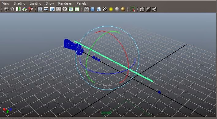
Then using the 'move tool' I pulled it away from the main barrel.

I then selected all the faces of the cylinder near the barrel.

I then clicked 'extrude'.

Using the 'Move tool' i pulled the face outwards and then upwards causing there to be a sharp bent edge. using the 'scale tool' i tried to make sure that the object did not go flat.

I then repeated that process three more times and I created this zigzag pattern in the top of my weapon. I also made sure that the last bit penetrated the sphere.

I then moved on to creating the handles of the weapon. To do this I started with another cylinder led it flat again with the 'rotate tool' and i scaled it so that it was just slightly larger than it needed to be.

I then pressed three and when to 'Modify' - 'Convert' and then to 'Smooth Mesh Preview to Ploygons'

This is what it looked like afterwards, it is smoother at the edges and also thinner, this is why i made the original cylinder just a little bit bigger.


I then went to work on the very end of the weapon. To do this I created a cube and i scaled it to make it longer vertically and i also thinned it around all sides.

Using the split tool.

I then added partitions in the object so that I can manipulate it easier. I then selected the faces at the top and bottom as you can see from below.

I then did the same with the bottom face making sure to make it a little bit shorter than the top, this is because that is what my design designates that I do for this object.

Then I pressed the 3 key on my key board and I got this smooth mesh preview of the object.

I then manipulated the the edges of the object using the 'edge' tool and then using the 'Move tool' and morphing the object into the more organic shape that I wanted.

I then modified it to the 'Smooth Mesh Preview to Plygons'.

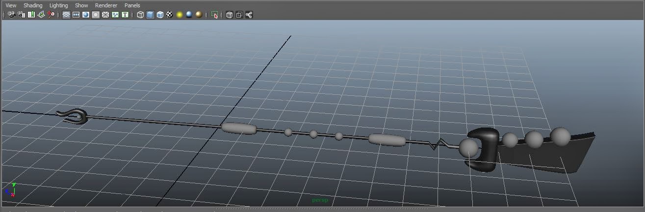
After that I then added the final physical features to my Naginata gun, this is three spheres that run along the top of the barrel, in descending size. The biggest at the top where the lasers shoot from and the smallest at the end of the barrel.

I then added the final touch of the 'Stun and Kill' buttons to the gun. I did this by creating a cube, then scaled it down a lot, after that I duplicated it and but them on the underside of the weapon and put them a little bit apart.

Now that my 3D model has been created, I shall start on the colouring and texturing.
For the textures that are on my model I gathered my secondary source from this website http://www.cgtextures.com/ this has an abundance of different materials and different colours.
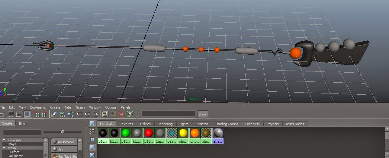
To start off with i split my working screen into two by clicking the 'persp/graph' button.

In the new window down below that has appeared I clicked on the drop down menu 'Panels' - 'Panel' - then to 'Hypershade', this is going to be where the colours/materials/textures are made.

Then as you can see from the image above there is a selection of different materials, the main ones that will be used in this are going to be 'Blinn' which has a shiny surface which could be used for plastic materials, 'Lambert' that could be used for cloth or other non shiny surfaces, and lastly 'Phong' and 'Phong E' These are the same except for 'Phong E' gives off more of a surface shine.

Then using my colour concepts that I have, I made a selection of the main colours that will be used. I am starting off with the colours because later it will be easier for me to texture when there are already base colours where I would like the base colours to be.

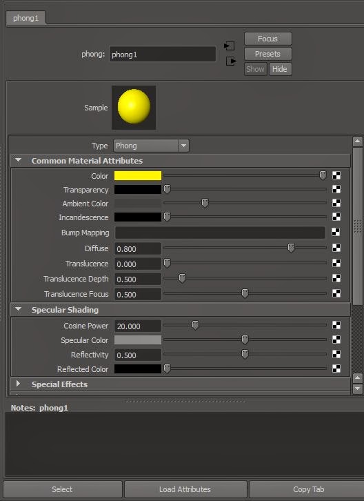
By double clicking a material a window will open on the right of the programme, then going to where it says colour, click on the area where there is colour (in this case the lack box) and then pick the colour that you want - I have chosen black.

Then select the areas in which the colour is going to be applied.

Then right click over the colour that you want in that area and click on 'Assign Material To Selecion'.

As can be seen, the colour has been applied to the object that was selected.

By using the shift key, I can select more objects at the same time.

Then by right clicking over the colour while they are selected you can colour more of the model at once.
I then moved on to the lower orbs and selected all the ones that I wanted to be the same material.

As you can see, these orbs have been made an orange colour.
I then changed the material a bit so that it was shinier and looked more reflective, I did this by using 'Phong E' instead of 'Lambert'.

After that I selected the handles and then using the same method as before but with the yellow colour that was created, they were covered in a yellow shiny material.

The orbs on top of the barrel were the next to be done - these were a little more complicated.

I clicked on the brown blinn material that I had then, going to the 'Transparency' slider I slid it to the right and made the material slightly see-though so it had a kind of glass vibe to it.

This is what it looked like on the model.

I then selected the barrel, right clicked and then selected 'face'. I then selected all the faces around the front of the model and made sure that all line was smooth were it will meet the black material.

Then while that was selected I wrapped the yellow material around the selected area.

Then for the object that is connected to the barrel, I repeated the same actions again.

As you can see there is a sharp time where the yellow meets black and that is exactly what I want.

Then for the 'Stun and Kill' Buttons I used the green and red materials, this was done separately for each button.

Now onto adding the textures to the weapon. Starting with the yellow double click it to bring up the window on the right of the programme.
Then go to the bit with the slider.
Then click this icon.

This window will then appear and this is giving you more options for materials and textures and things.

But since I have gathered my own images I am going to grab them from my folders. To do this just click the 'file' option.

Then the programme window on the right will change, you may have to scroll up, but when you see this bit where it says 'Image Name' click on the little folder that is to the right.

Then find the image that you want. Then click 'Open'

As you can see the yellow has changed to a more rusted colour that the texture I just picked out looked like.

Then right click over the texture and select 'Select Objects With Material' then, right click again and select 'Assign Material To Selection'.

This may then happen, but this is because it hasn't been set to that Textures can be seen.

So at the top of the window, there is a ball that has a checkered pattern on it and this is called 'Textured'.

You will then be able to see the textures that are applied to the model.

Now im going to change the uv's on my model but im going to do it a different way then using uv maps. First make sure that you are in the file editor.

Then go down to where the 'UV coordinates' drop down list is and then click on the bit where it looks like an arrow going into a box.
Then using the sliders, I changed the position on the frame and also of the UV.

Then after that I made it so that the front of a barrel looks like lasers can shoot out of it.

I then clicked on the orange material and then scrolled through the drop down list to 'Special Effects' and that says 'Glow intensity'.

I then used the slider to higher the glow factor of the selected area.
I then created another texture with a image of rubber with lines within it this is for the handles. Don't worry that the glow is not visible at this point in time, the model, later when rendered will show the glow.

As you can see the texture has formed nicely around the objects and makes them look like they have embossed grips.

Then I did the three orbs that are on top of the model, and to do this I clicked on brown glass material that was created earlier. Adding that texture to the image, this then turned out more of a grey. So t change that I went to the 'Colour Balance' drop down and changed the 'Colour Offset' to brown and that made it the correct colour.

This is the glass orbs fully textured to what I wanted them to look like.

I then moved on to making the the black texture. I did this like the others, for this one I also had to change the 'Colour offset' to a darker grey.

You can slightly see the metal grain running across the barrel from the texture that was added.

This is the fully textured model I have created.

Then to see what it would look like when it is rendered out I clicked 'Render the Current frame (Maya Software) button.

Then this window appears and shows my model in its current frame and shows the added effect of 'glow' that was added to the model earlier.

To so my render more professionally and clearly, I shall be putting in a camera angle into my 3D space where I want it to capture my 3D model.
To create a camera go to 'Create' - 'Cameras' and then 'Camera'.
While it is selected go to panels along the windows and seclect 'Look through Selected' and then manipulate the camera angel as you would while looking through the 'persp' view.I then clicked the 'Resolution Gate' button so that it would show me what area of the screen is going to be rendered.

Then I added spotlights to the scene. This is done by going to 'Create' - 'Lights' and then to 'Spotlight'.
While it is selected go to 'Panels' and click on 'Look Through Selected'.
Then using the circle that appears point it in the direction that you would like light to shine from. I have added three lights to this scene, a bright one, a softer one opposite it, and then one half way in between that is equally soft in its light projection.

To change them I double clicked the circles and the attributes window appears, for the main light i changed the colour to a pale blue and upped the 'Penumbra Angle' that has the light fade out at the edges.

Then scroll down to where it says 'Depth Map Shadow Attributes' this is because when there is a light shining directly on it, it will cast a shadow. So to do this select the tick box where it says 'Use Depth Map Shadows'.
I only used this for the main light, this is because /i did not want there to be two over lapping shadows in the scene.

This is the scene in 'persp' view, this had little models to show where the lights and camera are positioned.

This is the final render of my Sci-fi weapon in Maya.

I then saved the rendered image as a 'JPEG' and this is what it looks like as in a file format.

This is the end of the creation of my 3D model in Maya.
No comments:
Post a Comment